Building Sustainability into Control Systems > Radiant Panels
Introduction
Background
Control
Introduction
The radiant panels at 41 Cooper Square are a crucial means of regulating indoor temperature and comfort in the building. Inside of the panels are copper pipes which carry hot or chilled water to regulate optimal room temperatures.
The main benefit of the radiant panels is that, unlike forced air systems, they offer a more even distribution of the temperature within the room, resulting in indoor climates that feel more comfortable and less drafty. Furthermore, the specific heat of water is higher than the specific heat of air, which allows water to hold more energy per unit mass. This results in less transport losses and greater heat transfer to the room.
Most rooms in 41 Cooper Square, with the exception of the computer center classrooms on the 8th floor and some interior lab spaces, are equipped with radiant ceiling panels. Some lab spaces are only equipped with heating panels due to high air exchange rates negating the need for radiant cooling [1]. Radiant ceiling panels are not used in certain spaces due to associated risk with condensation, which can potentially damage electrical equipment. Radiant floor heating and cooling is installed in the lobby and exhibition space.
Background
Figure 1 shows a schematic of the operation of the two systems in a typical 41 Cooper Square classroom.
In Figure 1, the system components are: (1) Radiant Panels, (2) Air Valve Damper, (3) Electronically Actuated Two-Position Three-Way Valves, (4) Electronically-Actuated P-Controlled Two-Way Valves, (5) Radiant Hot Water, (6) Radiant Chilled Water, (7) Hot Water from Boiler Plant, (8) Chilled Water from Chiller Plant.
The heating and cooling systems are used to provide heated or chilled water to the radiant panels through heat exchangers. The heating and cooling streams do not mix, but instead meet at a 3-way valve junction which controls whether the system is in heating or cooling mode. Proportionally controlled two-way valves control the mass flow rate based upon the demand for heating or cooling. Only one of these two valves is open at a given time to prevent mixing of the two flows. Upon exiting the radiant panels, either hot or chilled water returns to the boiler or chiller plants, respectively.
Radiant System Design
Radiant systems are typically designed in the floor or in the ceiling of a building; in theory the walls can also be used but they are typically avoided to reduce the effects of gravity on the system, which can lead to problems [2]. The radiant panel systems that are used in 41 Cooper Square are hydronic, meaning that a working fluid is used as an emitter to provide heating or cooling to the panel surfaces. Electric systems involving the heating of wire may also be used, but these can only provide heating to a room and not cooling [3], and are expensive to operate.
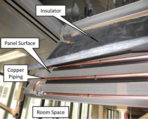
An interior view of a radiant panel is shown in Figure 2.

The insulation layer is placed above the radiant ceiling panels to absorb sound, and subsequently reduces thermal effects from the copper beams on the side of the radiant system not adjacent to the room [3]. The remaining space inside of the panel is air, which is heated or cooled from the radiant coils and transfers heat to or from the panel surfaces.
*Heat Transfer
Radiant panels provide heat (or cooling) to a room by directly heating up the room’s interior surfaces, resulting in a much greater sensation felt by the occupants than traditional forced air systems alone. Some basic knowledge of heat transfer concepts is needed in order to understand how the radiant panels affect the indoor temperature. Heat is transferred by means of three different mechanisms: Conduction, convection, and radiation. In a radiant panel system involving the passage of a working fluid through a pipe, all three of these modes of heat transfer are involved.
The extent to which the radiant system influences the actual temperature felt in the room is dependent on the mass flow rate of the water, fluid properties, and material properties. In the heat transfer course students will gain a more quantitative understanding of the heat transfer mechanisms and how these systems are designed accordingly.
Conduction is heat transfer brought about by direct particle interaction within a solid or fluid [4]. The heat transferred through conduction is proportional to the temperature gradient across a surface and the conductivity of the material. Ex: Metal pan heating a stove.
Convection is the transfer of heat between a solid surface and an adjacent fluid, taking into account both conduction and fluid motion [4]. Heat transfer through convection is proportional to the difference between the solid and the fluid, and a convection coefficient based on the type of convection taking place. Ex: Candle flame or furnace heating the air.
Radiation is the transfer of energy from electromagnetic waves, or photons of light. Thermal radiation is emitted by an object because of its temperature [4]. The extent to which heat is transferred by radiation is controlled by a constant called the emissivity, as well as geometric parameters between the two surfaces in question (in this case the radiant panel and a building occupant). Radiation is unique in that it exerts fourth-power dependence on absolute temperature (Kelvin or Rankine), meaning that changes in the panel temperature can exert a greater influence on the perceived room temperature. Ex: Heat from the sun or hands warming over a stove.
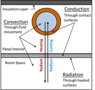
Figure 3 shows a simplified schematic of a single pipe cross-section in a ceiling radiant system, to illustrate how the heat transfer mechanisms work in a radiant system to heat up a room. In this view, the direction of water flow would be into or out of the page.

When the radiant system is in heating mode, some of the heat from the water is transferred to the copper piping through conduction, resulting in the pipe getting warmer. This heat is then transferred through an air gap inside the radiant panel until it hits the panel interior, which, like the copper piping, starts to heat up and transfers heat as conduction through a wall of uniform thickness. Finally, convection to the actual room space through the air occurs, making the room temperature feel warmer. In the case of radiant cooling, the entire process is reversed, with heat from the room being removed and transferred into the radiant panels, ultimately heating up the chilled water flow.
Although there is some radiation from the panel itself into the room, one should be careful not to quickly associate radiant panel systems with radiation, as it is not the primary heat transfer mechanism in operation.
Control
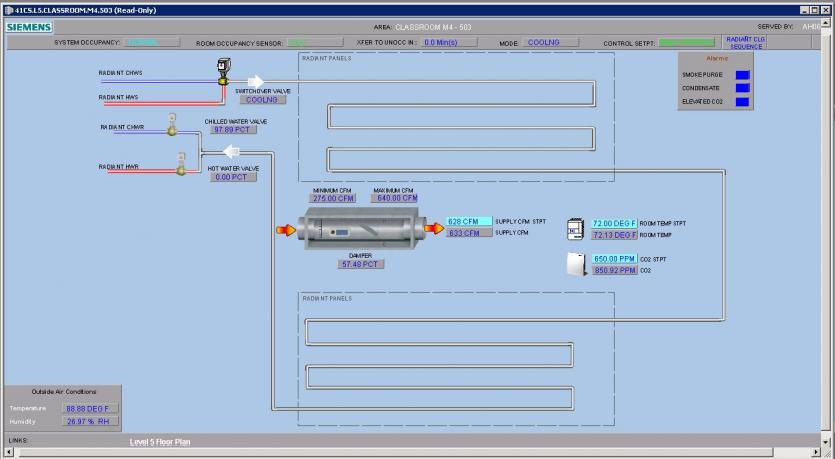
Whether the panels operate in heating or cooling mode is directed by a switchover valve, as seen in Figure 4.
Heating and Cooling Valves

The BMS regulates the flow rate of water through the panels. Three valves are used to control the radiant system: One three-way valve to determine the mode of the radiant system and two two-way valves to control the flow rate of the water through the system. These can be seen in Figure 1 (as items #3 and 4) and Figure 4 (as Switchover Valve, Chilled Water Valve, and Hot Water Valve).
Figure 4 shows a variable volume unit (VAV), whose air flow is subsequently affected by the heating or cooling demand as determined by the space temperature set point. The nominal air supply temperature is 55°F; thus during occupied mode, if the room is in heating mode, the VAV will decrease the flow of air to the space until the room temperature set point is met. Likewise, if the room is cooling mode, the VAV will increase air flow. If the room is unoccupied, the VAV is controlled using an unoccupied temperature set point.
Occupancy Sensing and Control
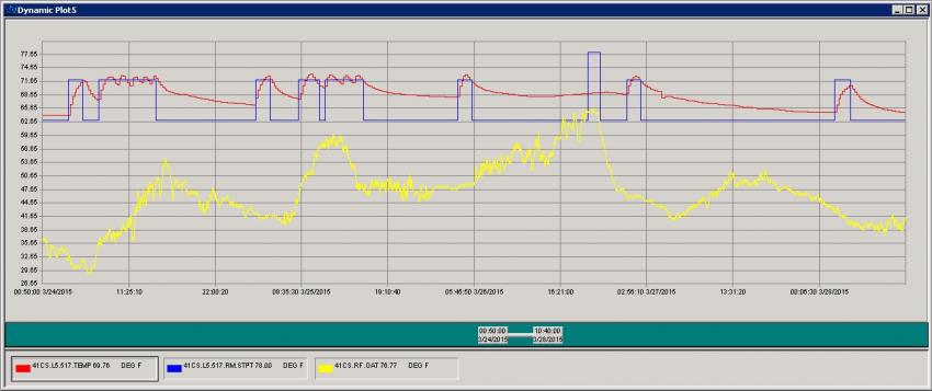
The spaces in 41 Cooper Square have occupancy sensors, which detect when spaces are unoccupied. During the winter the unoccupied set-point is 63° F (17° C) and during the summer the unoccupied set-point is 78° F (26° C). Once the system detects an occupant, the set-point is automatically changed to a typical occupied set-point of 72° F (22° C). Once the occupants leave the room, a timer counts down a specified time, e.g., 15-90 minutes, and if the space remains unoccupied the radiant panels are turned off, and the VAV dials the damper down to maintain a minimum airflow set-point. Figure 5 depicts a screenshot of the temperature set-point (in blue) and actual temperature (in red) of a typical office space over a four day period. Note, the system time response is first-order in nature and the time constant depends on factors such as the outside air temperature (in yellow) and occupancy, and could be used to determine optimal unoccupied temperature set-backs and countdown time to transfer to the unoccupied set-point.

Some spaces also have CO2 sensors, which detect the level of occupancy and are used as controller inputs for setting the supply airflow cubic feet per minute (CFM) as shown in Figure 4.
*Preventing Condensation
In the design and construction of 41 Cooper Square, condensation was a major concern with the radiant panels [1]. When operating in cooling mode, there runs the risk of the surface temperature of the copper tubing in the radiant panels falling below the indoor air dew point temperature. This would cause condensation, which could potentially damage electrical equipment in the room.
If condensation is detected in a room, sections of piping are equipped with sensors that will immediately close the supply valve of chilled water. The BMS will then alert the maintenance or facilities engineer to investigate the problem.
However, if condensation is detected in multiple zones, then all of these zones would have their radiant cooling systems shut down and the building water temperature would be raised by 2 °F. If the issue disappears within a specified time interval (~15 minutes), then the rooms’ radiant systems would start up again. If condensation remains an issue for some time, the entire building’s radiant system would shut down and the operator would then review the problem to ensure that condensation is not occurring. Once it has been confirmed that condensation is no longer a concern and the system is ready to restart, the building water will gradually decrease until it reaches the original temperature setting.

