Building Sustainability into Control Systems > Chillers
Introduction
Background
Control
Introduction
The chillers in Cooper Union’s 41 Cooper Square building, shown in Figure 1, supply chilled water that is to operate the building’s heat exchangers and air handling units. The chillers operate on a standard vapor compression cycle, using H-134a as the refrigerant. H-134a is considered a “green” refrigerant that does not contain CFCs (chlorofluorocarbons), chemicals used in older refrigerants that have been found to significantly deteriorate the ozone layer. 41 Cooper Square has two chillers, each with a 500-ton capacity [1] . This 500 ton capacity signifies that every day each chiller is capable of freezing 500 tons of liquid water at 0°C to ice which is roughly equivalent to the cooling capacity of 600 window-mounted air conditioners typically found in American homes1 [2].
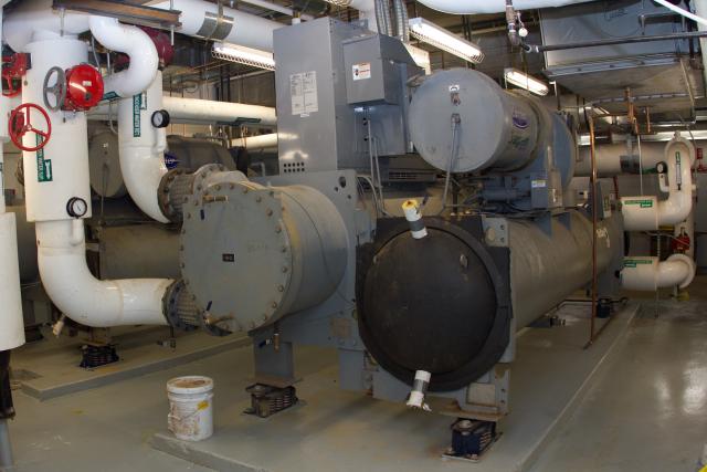
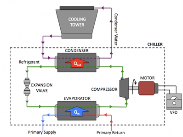
Figure 2 shows that the refrigeration system consists of three fluid streams: refrigerant, primary water, and condenser water. The refrigerant shown in green is pumped through the chiller’s main components in order to complete the vapor compression cycle. In the evaporator, the refrigerant absorbs heat from the primary water flow as it changes phase from liquid to vapor. This heat absorption process, represented schematically by the blue arrow, Qin, cools the primary chilled water supply flow, which is subsequently routed to the air handling units and heat exchangers. After passing through the evaporator, the refrigerant is passed through the compressor, where its temperature and pressure increase. Subsequently at the condenser, the refrigerant flow changes phase back from vapor to liquid. During this phase change the refrigerant rejects heat to the condenser water as represented by the red arrow, Qout. An evaporative cooling tower cools the condenser water after it has absorbed heat from the refrigerant.
Background
Vapor-Compression Refrigeration Cycle
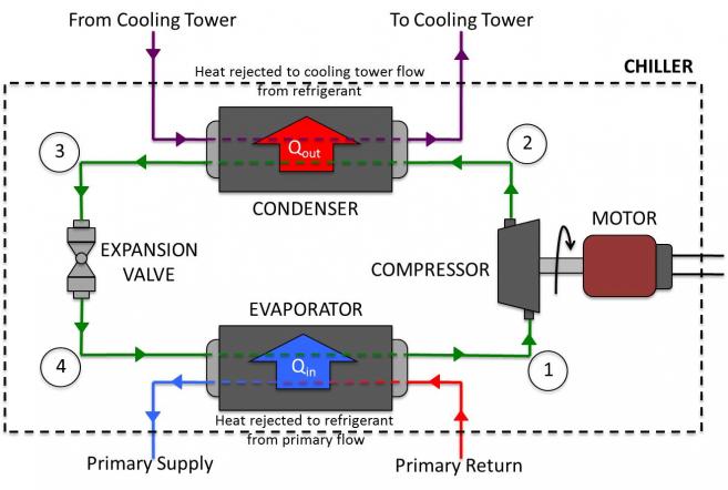
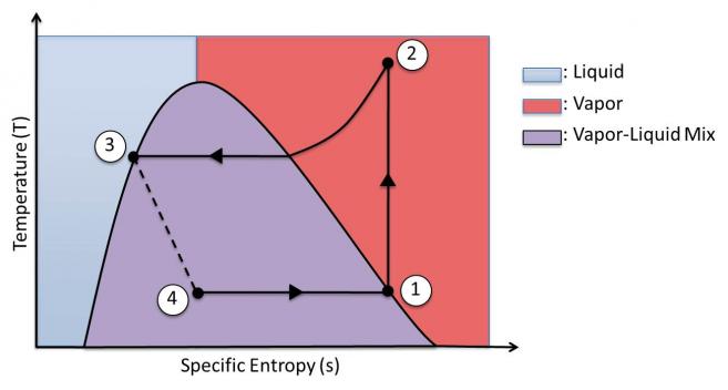
At State 1, the working fluid (refrigerant) is a saturated vapor. As it passes through the compressor (process 1-2), the pressure of the fluid increases, and the working fluid changes to a superheated vapor at State 2. This superheated vapor is passed through the condenser (process 2-3), where it rejects heat to the condenser water. After passing through the condenser, the fluid becomes a saturated liquid at State 3. This liquid is throttled through an expansion valve (process 3-4) where it flashes to a liquid and vapor mixture at State 4. This mixture is subsequently passed through the evaporator (process 4-1)where it absorbs heat from the primary water flow, thus reducing the temperature of primary chiller water supply for use in cooling the building. As the refrigerant absorbs heat, it becomes a saturated vapor at State 1, and the cycle repeats.
The performance of the refrigeration cycle is dependent upon the refrigerant’s enthalpy at all four states and the refrigerant’s flow rate through the cycle. By increasing the pressure rise through the compressor, the enthalpy of the refrigerant at States 2 and 3 is increased, and the cooling capacity consequently increases. Additionally, as the pressure rise through the centrifugal compressor is increased, the refrigerant mass flow rate increases, and the refrigeration cycle is able to cool larger quantities of water. Thus, it is possible to vary the pressure and mass flow rate of refrigerant throughout the cycle simply by controlling the compressor’s operating speed, allowing the chillers to satisfy fluctuating cooling demands.
Compressor
The chillers at 41 Cooper Square employ centrifugal compressors, which operate by exerting centrifugal force on a working fluid as illustrated in Figure 5.
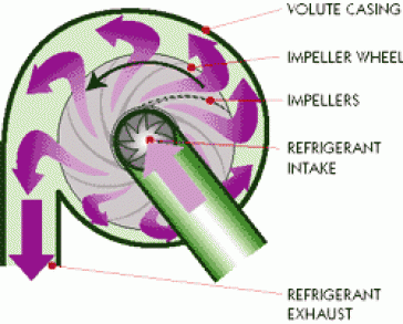
The compressors consist of two main components: the impeller and the volute casing. The refrigerant enters the compressor at the center of the impeller. As the impeller spins, it forces the refrigerant outside towards the walls of the volute casing. The refrigerant pushes against the walls, building up pressure until it reaches the exhaust vent and is released back into the system at a higher pressure. The impeller is driven by an AC motor that is controlled by a variable frequency drive (VFD). The VFD modulates the speed at which the impeller spins: The faster the impeller spins, the more force is exerted on the fluid and the pressure of the fluid is increased. This increase in impeller speed will also cause the compressor to force fluid through the refrigeration cycle at a greater rate (increase refrigerant flow rate and pressure at state 2 and 3). Both these actions have the effect of increasing the chiller’s cooling capacity. By varying the frequency of the VFD, the compressor speed is adjusted to vary the cooling capacity and power consumption of the refrigeration unit in response to fluctuating demands.
Evaporator and Condenser
Both the evaporator and condenser are heat exchangers. These devices transfer heat from the refrigerant flow to a water flow. In the case of the condenser, heat is rejected from the refrigerant and absorbed by the water that goes to the cooling towers. In the evaporator, the refrigerant absorbs heat from the primary water flow to supply the HVAC system with chilled water at 42° F (5.6 ° C) [4].
Both the evaporator and condenser are shell and tube type heat exchangers. In this type of heat exchanger, a series of tubes is encased in a large shell, as shown in Figure 6.
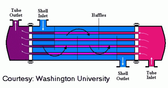
One fluid is passed through the exchanger’s tubes, while the other is passed through the shell. Heat transfer occurs through the walls of the tubes, keeping the two flows separate throughout. In the case of the chiller’s evaporator, the refrigerant is passed through the exchanger’s shell, while the primary water flow goes through the tubes. At this point in the cycle, the refrigerant is mostly a vapor and liquid mixture. Thus, a series of baffles is installed inside the shell in order to uniformly distribute liquid refrigerant while slowing the flow of this liquid [1]. These baffles are intended to maximize the amount of heat transfer that takes place in the exchanger.
The condenser works similarly to the evaporator, with refrigerant passing through the shell and condenser water flowing through the tubes. However, unlike the evaporator, the refrigerant passing through the condenser is primarily in the gaseous phase, exiting as a liquid towards the end of its passage through the device. Consequently, the specifications written for these condensers mandate that baffles be implemented to prevent direct impingement of refrigerant gases on tubes and to evenly distribute gas refrigerant over the length of the condenser [6]. Once again, these baffles were intended to maximize heat transfer and, thus, boost the system’s overall efficiency.
Cooling Towers
In order to bring the refrigerant from a superheated vapor to a saturated liquid, the condensers employ a flow of condenser water to absorb heat from the refrigerant. The building’s two cooling towers operate based on evaporative cooling. Inside the tower, condenser water is sprayed down a main shaft into an incoming flow of atmospheric air. Given that the atmospheric conditions are below 100% relative humidity, a small amount of the condenser water droplets will evaporate. As evaporation occurs, heat is absorbed from the main body of liquid in order for a small portion to overcome the latent heat of vaporization and become a vapor. This vapor is carried away in the airflow, leaving behind cooler water droplets, which are subsequently collected at the bottom of the tower and sent to the condensers. The condenser water produced in this manner is close to the wet-bulb temperature of the atmospheric air.
The cooling towers at the Cooper Union are of the cross-flow, induced draft variety as shown in the schematic and photo of Figure 7 and 8, respectively.
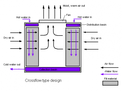
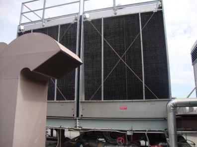
In order to control the temperature of the cooling tower flow to meet fluctuating cooling demands, both the flow rate of water and air through the tower are controlled. For example, if the water flow temperature supplied by the tower is higher than its set point, both air and water flow rates will be increased to increase the rate of evaporative cooling occurring in the tower. Conversely, if the water temperature is lower than the set point, the fans are turned off entirely and the water is allowed to simply drip through the tower at the minimum flow rate required by the condensers [6].
Control
The chillers in the Cooper Union’s 41 Cooper Square are designed to produce primary chilled water at a nominal temperature of 42 °F. In order to achieve this set point temperature, the building’s two chillers, two cooling towers, and various system pumps are operated in the most efficient combination possible.
When the BMS identifies that a radiant panel or air handling unit requires chilled water, a signal is sent to activate the primary chiller. At this point, an operator is required to approve the chiller start up due to safety concerns, and once approval is granted, the BMS goes through a long series of safety checks to ensure that the system powers on properly. For example, the chiller’s compressors are not activated until cold-water flow is detected through the condensers via differential pressure sensors. In this manner, the BMS prevents the chillers from overheating by ensuring that the condensers are working properly. With these checks complete, the chiller’s compressor is activated and primary chilled water begins to flow through the evaporator.
Most of the system critical components in the main chilled water system are controlled by Variable Frequency Drives (VFD’s). VFD’s modulate the frequency of the current that is sent to the AC motors that power pumps and fans throughout the system. By controlling the current frequency, it is possible to vary the motors’ power output and consumption.
The implementation of VFDs allows the BMS to control the flow produced by the cooling system’s pumps, fans, and compressors while managing their power consumption. This allows the cooling system to be adjusted to meet a wide range of loads efficiently. For example, if the primary or secondary return flow temperatures are too high, this indicates to the BMS that the building’s cooling demand is not being met. The BMS responds to this increase in demand by boosting the speed of the compressor (to increase the cooling capacity of the refrigeration cycle) while increasing the water flow through both the condenser and evaporator by ramping up VFD drives on the appropriate water pumps.
If the cooling load is low, a single chiller is used to supply the building’s chilled water. However, if the demand for chilled water increases to a level where the lead chiller is unable to maintain the supply temperature set point of 42 °F or if the tons of chilled water (as calculated using the chilled water flow meter and secondary supply/return chilled water temperature sensors) is at the chiller’s capacity, the BMS then brings the second lag chiller online [6]. Recall that one ton of cooling capacity is equal to 3.5 KW or 12,000 Btu/hr.
Using this control sequence, the second ‘lag chiller’ is brought online to meet higher cooling demands. It is important to note that the lead chiller is allowed to reach steady state operation before the lag chiller is brought online. When the chillers are first turned on, their energy demand peaks as the system takes tepid refrigerant and begins the cycle. Con Edison must be prepared to meet these peaks in energy consumption at any time, requiring that large infrastructural assets be allocated for the building’s operation, thus Con Edison electricity charges are based on the peak demand . By not turning on both chillers at the same time, this peak in energy consumption is reduced, and operation costs are brought down significantly.
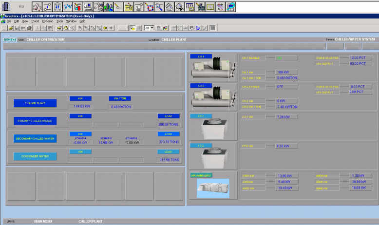
Screenshots of the control panels for the chiller plant are shown in Figures 9 and 10.
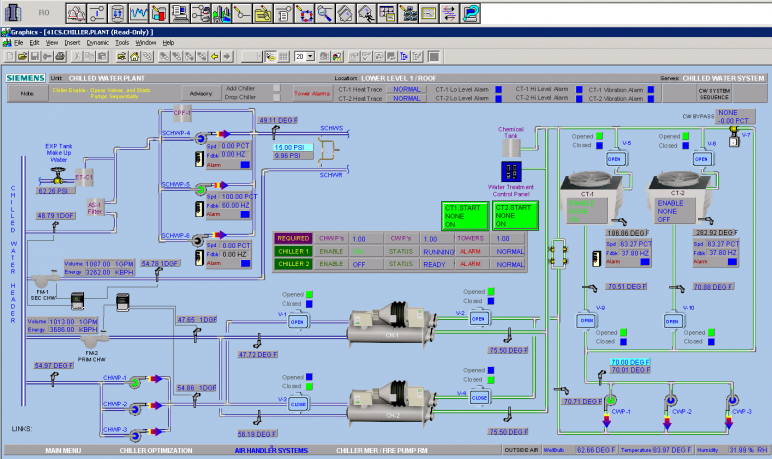
As shown in the BMS Overview, the system consists of two chillers, two cooling towers, and an extensive plumbing system. At the moment that this shot was taken, on June 29th, 2011, the outside air temperature was 84 °F at 32% relative humidity. Given these outdoor conditions, the building required the operation of only a single chiller to meeting cooling demands. Thus, the feedwater valve on Chiller 2 is in the ‘closed’ position. Primary water flow enters Chiller 1 at 54.86 °F and exits at 47.72 °F. The pump ‘CHWP-1’ provides a flow of 1013.0 GPM through the chiller, as registered by flow meter, ‘FM2 – PRIM CHW’. The BMS’s enthalpy minimization algorithms calculate that this flow of chilled water provides 3686.00 KBtu/hr (1080 KW) of cooling power.
The BMS Overview also depicts the operation of the cooling towers necessary for the refrigeration cycle’s operation. At the instant pictured, both cooling towers are running in order to meet the cooling demand of Chiller 1’s condenser. Water enters these cooling towers at 75.50 °F and exits at roughly 70.0 °F and is pumped by condenser water pumps (in this case, CWP-1) back through the condenser.
This BMS Overview also displays the pumps that drive the secondary chilled water flow. At the moment shown, only one of the three pumps is pumping secondary chilled water through the building’s radiant panels (pump SCHWP-5).
The BMS Chiller Plant Optimization panel shows the power consumption and chilled water production of the entire cooling system. At this time, the chillers, cooling towers, and various pumps were consuming a total of 144.83 KW of power, while meeting a 306.08 ton cooling load (equivalent to 1076 KW). To the right, all components of the chilled water system are shown individually. It can be seen that only Chiller 1 is operating, consuming 109 KW of power to meet the entire 306.08 ton load. Finally it can be seen that both cooling towers are on, consuming roughly 7.5 KW of power to operate their fans and pumps.
The BMS provides the user with all parameters necessary to monitor the energy consumption and performance of the chilled water system. Using this system of sensors and data collection, energy-saving decisions can be made using a series of control algorithms.
1Average air conditioners have a cooling capacity of about 10,000 Btu/hr (~3 KW). 1 ton = 3.517 KW = 12,000 Btu/hr.
Enthalpy - A thermodynamic property equal to the internal energy of the system plus the product of pressure and volume: h = u + pv [2].
Latent heat of vaporization – The energy required to bring a substance from the liquid to vapor state [9].
Wet bulb temperature – The temperature of air that has been completely saturated with water through an adiabatic process [2].
[1] GMP Set - The New Academic Building of Cooper Union – Centrifugal Water Chillers. Syska Hennessy Group, New York, NY, 2007. pp. 15684-5.
[2] Y. Çengel and M. Boles. Thermodynamics: an engineering approach, 7th ed. New York, McGraw-Hill, 2011.
[3] Compressors: How They Work. Four Seasons Controlled Climates Ltd. (2011, June 11). [Online Manual]. Available at: http://www.fscc-online.com/%22Passing%20Gas%22-article/passing_gas.html
[4] GMP Energy Report – The New Academic Building of Cooper Union. IBE Consulting Engineers, Camarillo, CA, 2006. p. 16.
[5] C. Halego. (2011, June 11) Basics of Industrial Heat Transfer. Chemical Engineering of Washington University. [Online manual] Available at: http://www.cheresources.com/heat_transfer_basics.html/
[6] G. Sampton. Sequence of Operation – The New Academic Building of Cooper Union. Morphosis Architects, Los Angeles, CA, Rep. 15959, June 2005. p. 18, 21.
[7] http://www.iklimnet.com/expert_hvac/cooling_tower.html
[8] What is a Cooling Tower? Cooling Technology Institute Home. (2011, July 1). [Online Article]. Available at: http://www.cti.org/whatis/coolingtowerdetail.shtml.
[9] R. Howell, H. Sauer, and W. Coad. Principles of heating, ventilating, and air conditioning: a textbook with design data based on the 1997 ASHRAE handbook--Fundamentals. Atlanta, American Society of Heating, Refrigerating and Air-Conditioning Engineers, 1998.

