Building Sustainability into Control Systems > Cogeneration
Introduction
Benefits
Operating Modes
Introduction
One of the innovative green technologies at 41 Cooper Square is the cogeneration system. Located on the mechanical roof of the building, the cogeneration system supplies the building with electricity and useful heat.
Cogeneration is the use of a heat engine (whether a reciprocating engine, gas turbine or other), to simultaneously generate mechanical power (usually used to generate electricity) and useful heat. The production of electricity by a heat engine requires heat input at a high relative temperature and heat rejection at a lower temperature. In practice, the heat rejection is normally dissipated to the local environment, and is therefore wasted. Rather than waste this heat, cogeneration uses the heat rejection from the engine to generate steam and/or hot water, which can then be used for space heating or process heating in industrial applications. Large buildings and campuses have used cogeneration to reduce their electricity demands from the local utility while simultaneously reducing operating costs.
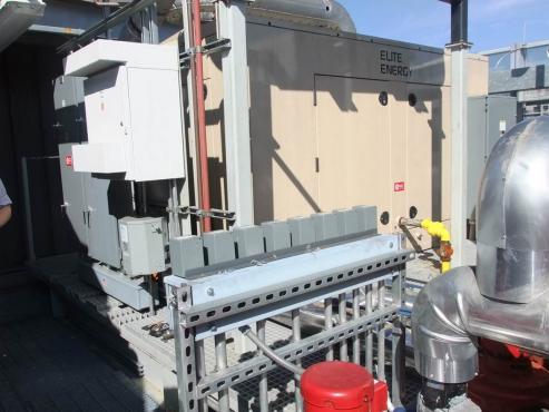
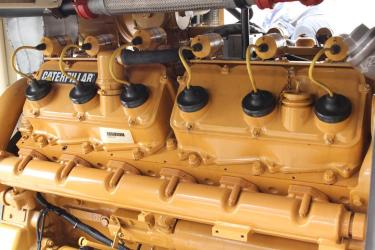
Cogeneration is not limited to large buildings and campuses. Cogeneration can be used for small office buildings, schools, and apartment buildings. The Cooper Union is such an example. Two cogeneration units are installed, one on the roof of the Foundation building and the other on the roof of 41 Cooper Square. The 41 Cooper Square cogeneration plant enclosure is shown in Figure 1. The 349 hp natural gas, reciprocating engine and 250 kW generator inside the enclosure are shown in Figure 2.
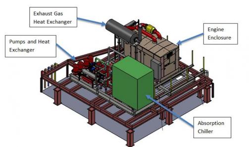
An isometric of the cogeneration plant is shown in Figure 3. The engine enclosure includes the engine and generator. The exhaust gas heat exchanger is shown above the engine enclosure. Depending on seasonal demands, the heat byproduct from the cogen engine can have multiple uses. In winter, the hot water heat exchanger supplies hot water for heating. In summer, the heat byproduct from the engine is used in an absorption chiller to supply chilled water for cooling. When there is insufficient demand for some or all of the waste heat (typical of spring and fall), some or all of it can be rejected to the condenser water via a heat dump heat exchanger.
Benefits
Onsite cogeneration, also known as combined heat and power (CHP), is more efficient than purchasing electricity from the utility grid since otherwise wasted thermal energy is captured for use. Consider a case study where a building that requires 35 “units” of electricity and 45 “units” of heat as shown in Figure 4 [2]. The conventional method to meet this demand is to purchase electricity and gas from a utility company, represented on the left side of Figure 4. Use of cogeneration to meet the building’s demand is represented on the right side of Figure 4.
Using the conventional approach, the building’s 35 “units” of electrical demand are met by purchasing electricity from the electrical grid. The grid has an assumed transmission efficiency of 88% [3], requiring the power plant to produce 40 “units” of electricity to meet the building’s electrical demand of 35 “units”. In turn, the power plant requires 115 “units” of fuel input, a 35% electrical efficiency, to produce the 40 “units” of electricity. The building’s 45 “units” of heat demand is met by purchasing 55 “units” of gas from the utility and firing an onsite boiler with an assumed thermal efficiency of 82%. Overall, the building’s 80 “units” of required energy are met by 170 “units” of fuel input. The overall system efficiency (energy delivered to energy input) is 47%. The remaining 53% of input energy is rejected to the environment (at the power plant, via transmission losses and at the local boiler).
Using a combined heat and power system, the building’s 35 “units” of electrical demand are met by 100 “units” of fuel input assuming an electrical efficiency of 35%. The building’s 45 “units” of heat demand is met from the same 100 “units” of fuel input to the CHP system; thus, the heating efficiency is 45%. Overall, the CHP system requires an input of 100 “units” of fuel to meet both electrical and thermal demands yielding fewer losses to the environment (20%) and an increased overall efficiency of 80%.
41 Cooper Square Cogeneration Unit Overview:
Figure 5 shows a schematic of the engine enclosure at 41 Cooper Square at nominal operating conditions. Natural gas from the utility company is used to power the 349 hp (260 kW), V-12 naturally aspirated, spark ignition reciprocating engine. At full load, the engine consumes 27.8 therms per hours (815 kW) of fuel energy to drive the 250 kW electric generator at 1800 rpm. 1,569,000 Btu per hour (460 kW) of useful heat are recovered from the engine water jacket and the exhaust gas. Therefore, at full load, 31% of the input chemical energy is converted to electrical power, 56% is converted to usable thermal energy (heating power). The remaining 13% is lost to the environment [4].

Jacket water, a mixture of water and glycol, circulates through the engine block cooling the engine while reclaiming heat energy from the engine. The heat from the jacket water is transferred to the cogen hot water via the engine jacket heat exchanger. Typically cogen hot water enters the enclosure at a rate of 125 gallons per minute and a temperature of 170oF (76.7oC). The heat recovered from the engine jacket brings the cogen hot water temperature up to 187oF (86.1oC). The jacket water loop is kept separate from the cogen hot water loop to prevent contamination. Additional heat is reclaimed from the engine exhaust; a shell and tube heat exchanger transfers heat from the exhaust gas to the cogen hot water, bringing the water temperature up to 196oF (91.1oC).
*Operating Modes
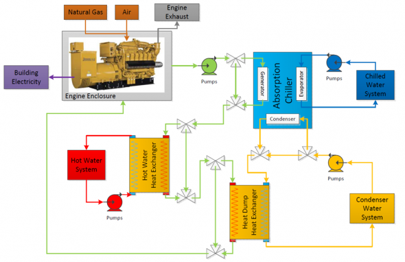
Depending on seasonal heating and cooling demands, the cogeneration plant has different operating modes. Figure 6 depicts a schematic of the equipment and cogeneration process.
*Heating Mode (Winter)
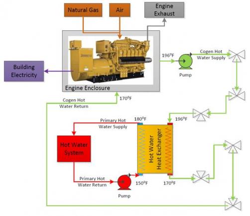
When the building requires heating (mostly during the winter months), the cogeneration unit is capable of supplying hot water for space heating. Figure 6 shows the process diagram for this operating mode.
The hot water heat exchanger transfers heat from the 196oF cogen hot water to the building’s primary hot water, raising the hot water temperature to 180oF from 150oF. This hot water is used in the building’s radiant ceiling panels and air handling units.
*Cooling Mode (Summer)
During the summer months, the building requires cooling. Hot water from the cogen is used to drive an absorption chiller to produce chilled water. Figure 8 shows the process schematic for when the absorption chiller is operating.
The absorption chiller, shown in Figure 9, is designed to supply 44oF chilled water for use in the building’s radiant ceiling panels, air handling units, and fan coil units. Condenser water is supplied to the absorption chiller to remove the heat from the refrigerant.
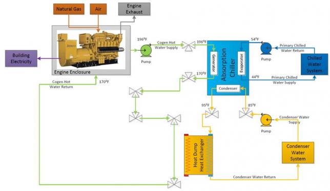
Absorption chillers run on a similar set of principles as the vapor compression (centrifugal) chillers; high pressure liquid refrigerant is throttled to low pressure (and therefore temperature) where the cooling effect occurs. However, rather than using a compressor to pressurize the refrigerant, the absorption chiller dissolves the vapor refrigerant into a carrier fluid. A pump, which requires much less work than a compressor, is used to pressurize the solution. Heat is then applied to the solution to separate the vapor refrigerant from the carrier fluid. The refrigerant then passes through a condenser, throttling valve, and evaporator as it would in a vapor compression cycle.
*Generator Mode
During periods when there is minimal cooling or heating demands on the building, there is no demand for the available thermal energy from the cogeneration unit. Figure 9 shows the process diagram with the cogeneration system operating in electrical production only mode. In this operating mode, the system generates electricity only and the engine heat is rejected to the condenser water and cooling towers via the heat dump heat exchanger.
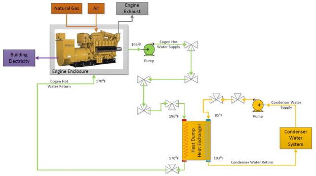
In this operating mode, the heat energy produced by the engine is wasted, as it would be in a remote power plant. When operating in this mode, the system is acting as an electric generator, not as a cogenerator. There is no simultaneous production of electricity and useful heat.
*Spring and Fall Modes
The cogeneration system uses engine heat for heating hot water or for cooling water in the absorption chiller, in the winter and summer seasons, respectively. Occasionally, the demand for hot water may not be enough to remove all the heat from the engine. Per design conditions, the engine inlet water temperature should not exceed 170oF. In order to maintain the inlet water temperature, excess heat is rejected to the environment via the condenser system. Under these conditions, the cogeneration plant operates in combined mode, in which a portion of the heat is used for heating hot water and the remainder of the heat is rejected to the environment.
Figure 11 shows the process diagram for when the cogeneration system operates in this mode. Three way valves before the hot water heat exchanger and heat dump heat exchanger control the flow rates (and consequently the return water temperature to the engine) through the heat exchangers. The valves allow a continuum of operating conditions with full heat utilization (heating mode) at one end and no heat utilization (thermal dump mode) at the other end.
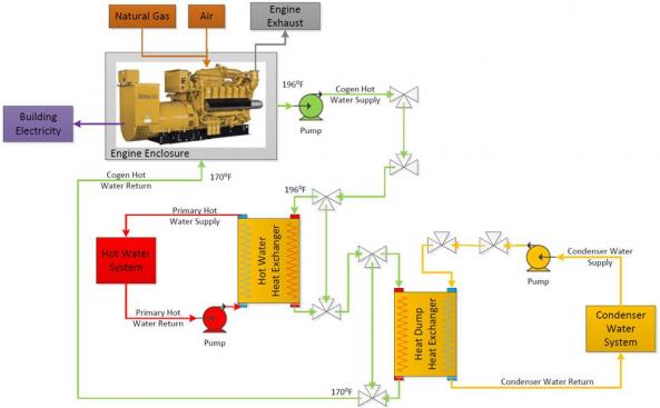
The cogeneration system can operate in other modes such as cooling and thermal dump or less frequently cooling and heating.
[1] S. One, “NYSERDA Design Submission,” 2010.
[2] P. a. L. B. H. P. Milton Meckler, Sustainable On-Site CHP Systems, McGraw-Hill, 2010.
[3] E. Energy, 250 kWe G3412NA CATERPILLAR Engine Spec Sheet, Carson City: Elite Energy.
[4] L. Hymann, "Combined Heat and Power: Design through Operations," in ASHRAE, New York City, 2014.
The source of the cogeneration page and more details can be found in Master’s thesis Technical and Economic Assessment of Cogeneration in an Urban Academic Building, Jonathan Rodriguez, 2014. Click here for more info.


