Building Sustainability into Control Systems > Heat Exchangers
Introduction
Background
Control System Overview
Introduction
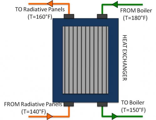
In 41 Cooper Square, the boilers and chillers supply primary water used to heat or cool the building. However, the water supplied by these systems is not directly routed to the radiative copper piping. Instead, a secondary flow of water is used throughout the network of radiant panels. In the case of heating, plate and frame heat exchangers are used to transfer heat from the primary hot water (from the boiler) to a secondary flow that supplies hot water to the radiant panels for heating. In order to cool the building, heat is rejected from the secondary flow to the primary chilled water supplied by the chillers. Both the heating and cooling systems have their own heat exchanger, which supplies hot and cold secondary flows that are routed to specified locations throughout the building. Figure 1 is a photograph of a chiller-side heat exchanger and Figure 2 is general schematic of a heat exchanger with temperatures typical of the heating mode.
Background
Plate and Frame Heat Exchangers:
There are many different types of heat exchangers, all utilizing different geometric configurations in order to achieve different design objectives. In a plate and frame heat exchanger, a series of parallel plates are joined together with equidistant gaps between them. Each of the two working fluids is passed through alternating chambers, maximizing the surface area over which heat can be transferred via conduction through the metal plates. This flow pattern is shown in Figure 3, provided by a manufacturer of industrial heat exchangers similar to those used in 41 Cooper Square.
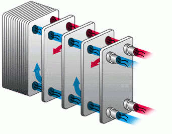
The two fluids in the heat exchanger are never mixed, creating two completely independent flows. Using plate and frame heat exchangers has the advantage of allowing the boiler (or the chiller’s evaporator) pressure to remain relatively low, as the primary flow does not have to be routed throughout the building’s radiant panels. Additionally, the secondary flow can more easily be routed to different parts of the building in response to changing cooling and heating demands without affecting the operation of the boiler (or chiller).
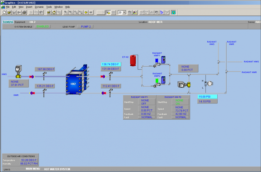
The secondary flow is circulated throughout the building’s radiant panels using the two pumps labeled 'HWP1’ and ‘HWP2’ shown in Figure 4. These pumps both are controlled by Variable Frequency Drives (VFDs) that allow the BMS to regulate the flow rate produced by each pump. The BMS adjusts the flow produced by the pumps to maintain a differential pressure of 15 psi in the secondary water loop (as measured by the differential pressure sensor Figure 4) [2].
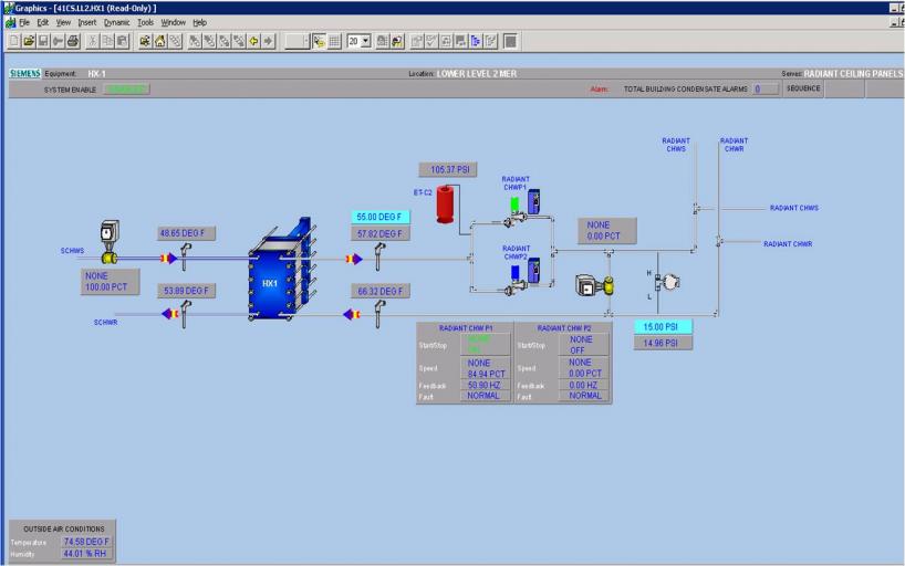
The heat exchanger used in the building’s cooling system (Figure 5) uses primary chilled water from the chiller (or from the absorption chiller in the cogeneration plant or from the water-side free cooling plate and frame heat exchanger) to cool secondary chilled water flow for use in the radiant panels. To avoid condensation, the BMS monitors the secondary chilled water supply temperature, indoor air temperature, and humidity. The radiant panel surface temperature is set to the greater of 3°F above dew point or 55°F to avoid condensation.
The flow produced by the pumps is routed to individual radiant panels using a large array of valves. Three way-valves in each room are individually controlled by the BMS to switch between allowing hot and cold secondary flow to enter the radiant panels. At the outlet of the radiant panels in every room, there are two servo valves, one for the hot and cold secondary return flows. By adjusting the position of these outlet servo valves, the flow rate through the radiant panels can be controlled while keeping the hot and cold secondary flows separate. The BMS panel of Figure 6 below shows the three-way valve that controls the radiant water inlet flow, and the two servo valves regulating the outlet flow in a classroom (505).
Control System Overview
The purpose of the heat exchanger is to produce secondary water flow at a specified temperature. The secondary flow rate is controlled as a function of differential pressure in the secondary flow loop. For example, if heating demand in the building increases, more radiant panels will be opened, and the differential pressure in the secondary hot water loop will fall due to the effective decrease in flow resistance. A differential pressure sensor detects this decrease in pressure (or "head"), and the BMS responds by increasing the operating speed of the secondary hot water pumps to increase flow rate and maintain a constant differential pressure of 15 psi in the secondary loop [2]. With the secondary flow rate controlled as a function of differential pressure, the controlled (or process) variable in the heat exchanger system is the secondary flow output temperature.
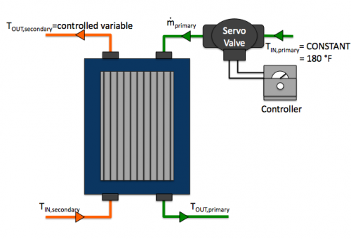
The secondary flow exit temperature is controlled through modulation of the primary mass flow rate. It should be noted, however, that this mass flow rate modulation would also affect the exit temperature of the primary flow. By increasing the primary mass flow rate, more heat transfer will occur, but the primary flow itself will exit at a higher temperature. As the hot primary flow passes through the heat exchanger more rapidly, it does not remain in contact with the cool secondary flow long enough to experience a large temperature drop. It is counterintuitive for this higher exit temperature to result in greater heat transfer, but physical laws (the enthalpy of water at these operating ranges) dictate that mass flow rate, not fluid temperature, has a dominant effect on heat transfer processes.
Since the primary flow comes out of the heat exchanger at a higher temperature at these high flow rates, it will require less fuel to be heated back to the 180 °F set point in the boiler. The BMS takes this information into consideration, determining primary flow rates that will produce secondary flow at the necessary temperature to meet thermal loads, while minimizing fuel consumption in the boilers by maximizing the primary flow’s exit temperature from the heat exchanger [2].
Variable Frequency Drive: Device that modulates the frequency of the current input to an AC motor (usually driving a pump or fan) in order to control the motor’s speed and power consumption.
Enthalpy: The sum of a fluid’s potential and flow energy. This measure of flow energy is covered thoroughly in Thermodynamics and Heat Transfer.
[1] http://www.dhtnet.com/plate_frame_heat_exchangers_as.htm
[2] Gruzen Sampton, Sequence of Operation – The New Academic Building of Cooper Union, Morphosis Architects, Los Angeles, CA, Rep. 15959, June 2005. p. 20.
[3] GMP Energy Report – The New Academic Building of Cooper Union, IBE Consulting Engineers, Camarillo, CA, 2006, p. 16.

