Building Sustainability into Control Systems > Rainwater Harvesting
Introduction
Background
Control
Introduction
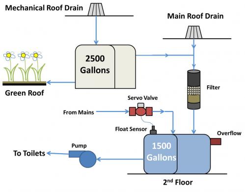
The rainwater harvesting system at 41 Cooper Square collects rainwater and condensate from the roof, which is used to irrigate the green roof garden and supply water to all of the toilets below the second floor. The bathrooms on these floors contain roughly 25% of the total fixtures in the building. Nearly 200,000 gallons of water can be reclaimed annually through the system [1]. The system saves clean water and also prevents storm water run-off. The system is relatively simple and depends primarily on gravity to distribute the water with the exception of three pumps which supply water to the toilets.
Figure 1 shows an overview schematic of 41 Cooper Square’s rainwater system.
*Background
Buildings consume around 20% of water resources [2]. Furthermore, HVAC features account for nearly one-third of the total water consumption in these buildings. Therefore, the harvesting of a natural source such as rainwater can benefit both the building and the environment. Storing the rainwater helps to save water, reduces the demand on the sewer system, and reduces polluted runoff to rivers and lakes [3].
41 Cooper Square has a green roof on the 8th floor, which is partially irrigated by the rainwater. The green roof also captures storm water which helps to reduce runoff, preventing excessive buildup of water in the sewer system. The roof also contributes to better outdoor climates during the hotter seasons capturing heat that would otherwise go to the roads or sidewalks, a phenomenon known as the “heat island effect” which explains why urban areas feel hotter than rural areas.
*Water Collection
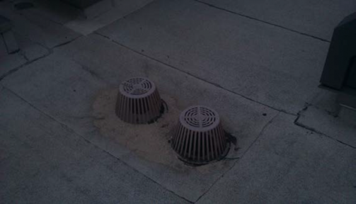
41 Cooper Square’s rainwater harvesting system employs two methods of collection. Water is collected from the eighth and tenth floor roofs of the building (Figure 1) during periods of rain. The drains are covered by cages to filter out large debris and empty to the tanks on the lower floors as shown. The 8th floor roof, which is shown in Figure 2, is 2000 square feet and empties to the green roof holding tank. The 10th floor roof is 8000 square feet and empties to the main tank.
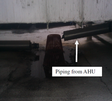
The second method of collection comes from the air handling units used to condition incoming air to the building. The humidity of the air supply is controlled and as moisture is removed from the air, the resulting condensate is also fed into the drains on the roof, as is shown in Figure 3. The amount of water collected is smaller than for rainfall, but the air handlers run constantly.
*Control
Unlike most of 41 Cooper Square’s other features, its rainwater system cannot be viewed in the BMS directly. However, it still employs various sensors and monitors to maintain water levels and ensure an adequate supply.
*Upper Tank
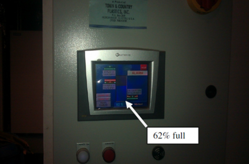
There are two storage tanks for rain water collection. A 2500 gallon tank located on the 10th floor receives water from the mechanical roof and provides irrigation for the green roof. It can be monitored by a digital display which shows the percentage full (Figure 4). The overflow from the upper tank goes to a 1500 gallon lower tank.
*Lower Tank
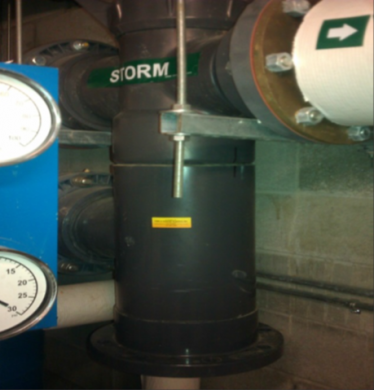
Water released from the upper tank combines with water collected from the main roof and passes through another gravel filter that is designed to remove large particles of debris that may be present from the roof (Figure 5). It then empties into a 1500 gallon tank on the 2nd floor of the building (Figure 6).
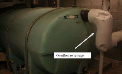
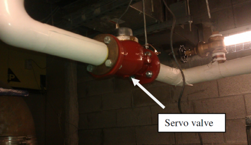
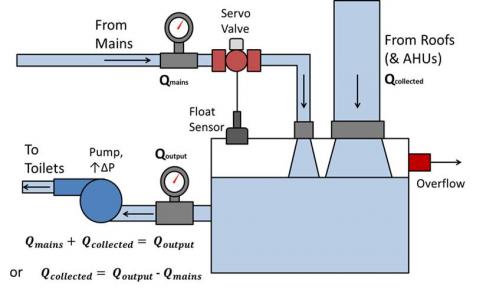
The lower tank has an additional input from the city water mains to maintain water level in case of low storm water. The lower tank has a similar digital display as the upper tank, but the lower tank also has an electronic sensor to detect tank level for simple on/off control. When the water level falls below a certain point, the sensor sends a signal to the control computer, which opens a servo valve (Figure 7) that fills the tank with mains water until the level reaches the required point.
The output from the 1500 gallon tank is sent through three pumps which supply it to the lower level bathrooms. The water supply cannot be fed by gravity alone due to the number of fixtures in the bathrooms which result in pressure losses.
To estimate the total amount of water reclaimed (which is equal to the amount collected from the roofs), flow meters are located on both the incoming supply from the city mains as well as the output from the tank to the bathrooms. The piping which empties the collected water into the tank (the white pipe in Figure 7) is of 8” diameter. Because a flow meter for such a large pipe is prohibitively expensive, the two flow meters mentioned were installed, and their difference represents the total collected water input to the tank.
- Reich, Holly. "Cooper Union's Green Roof Catches Rain Water." Daily News [New York] 16 May 2012, Big Town Going Green sec.: 32. Print.
- (2010). ASHRAE GreenGuide - The Design, Construction, and Operation of Sustainable Buildings (3rd Edition). American Society of Heating, Refrigerating and Air-Conditioning Engineers, Inc.. Online version available at: http://app.knovel.com/hotlink/toc/id:kpASHRAE71/ashrae-greenguide-design-2
- Elliott, Sara. "How Rain Barrels Work" 17 December 2008. HowStuffWorks.com. http://home.howstuffworks.com/rain-barrel.htm 24 June 2014.

