Building Sustainability into Control Systems > Water-side Free Cooling
Introduction
Background
Introduction
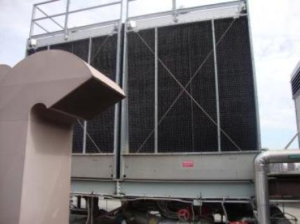
The academic building at 41 Cooper Square has many innovative features to reduce its energy consumption and environmental impact. Chief among these is the water-side free cooling feature utilized by the building’s cooling system (Figure 1).
Even during winter months, some parts of the building, such as the computer centers and some high occupancy classroom or laboratory spaces, must be cooled. When outdoor air temperatures are below ~55 °F and above 32°F, the cooling towers can be used to supply primary chilled water at a nominal set point temperature range of 42-47 °F. This method of cooling requires much less input power than the operation of the chillers. Figure 2 illustrates the water-side free cooling system.
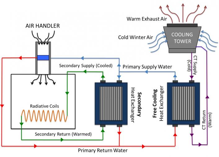
The schematic shows that the water-side free cooling system consists of two flows: the primary and condenser water flows. Using evaporative cooling, the cooling tower chills a flow of condenser water that is passed through a 350-ton plate-and-frame heat exchanger. In this Free Cooling heat exchanger, the condenser water from the cooling tower absorbs heat from the primary water flow. Subsequently, this chilled primary flow is used in the same manner as the primary flow normally supplied by the chillers: some is sent to air handlers, while the rest is passed through a secondary heat exchanger to cool the secondary chilled water flow utilized in the building’s radiant panels. Effectively, the water-side free cooling system allows the cooling towers to function as the building’s chillers. However, the cooling towers use atmospheric conditions, rather than a mechanically driven refrigeration cycle, as a heat sink to cool the primary water flow. This method of evaporative cooling is inherently more efficient, allowing the building to meet cooling needs without the need to operate large chiller plants.
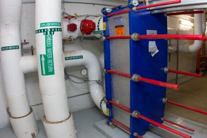
The Free-Side heat exchanger serves two distinct purposes. First, it allows the cooling tower to function in the same manner as the chillers, cooling a closed-loop primary water flow. This method of operation allows the water-side free cooling system to utilize the same plumbing network that is normally serviced by the chillers, effectively reducing installation costs. Secondly, as water is exposed to outside air in the cooling towers, it becomes contaminated with pollutants. Particularly, car exhaust gases commonly found in New York City air, can make the water acidic, and consequently corrosive. In order to combat this contamination problem, the cooling tower flow is treated with chemicals. However, if this tainted water were used directly as a primary chilled water flow, it would have the potential of causing significant damage in air-handlers and other equipment throughout the building. Thus, the Free-Side heat exchanger allows the cooling tower flow to be treated as a separate, closed system that can easily be monitored and maintained with little consequence to other systems.
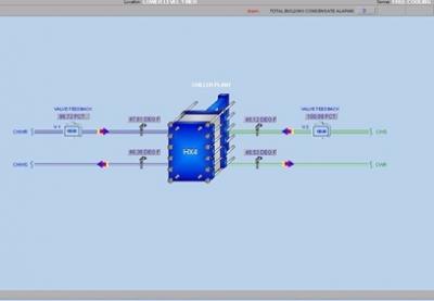
In the BMS Free Cooling Panel shown in Figure 4 when the outside air was 42°F with 45% relative humidity, the cooling tower flow, depicted in green, enters the heat exchanger at 45.32 °F and exits at 48.53 °F as it absorbs heat from the primary water flow, shown in blue. The 3.21 °F temperature rise in the cooling tower flow allows the primary water flow to be cooled by 1.25 °F, from 47.61 °F to 46.36 °F. Although this temperature change in primary flow may seem small, the resulting change in water’s enthalpy content provides enough thermal energy to meet the building’s cooling demands. It should also be noted that the BMS panel shows the Free Cooling heat exchanger running under full load conditions, with the servo valves controlling both the cooling tower and primary chilled water flows opened to 100%.
*Background
The water-side free cooling system at 41 Cooper Square effectively utilizes the cooling tower to meet the building’s chilled water demand. In order to properly size and implement this system, it is necessary to determine the cooling towers’ cooling capacities. However, the cooling tower’s cooling capacity changes according to atmospheric conditions, since it relies on outside air to act as a heat sink. Consequently, the cooling capacity of the towers is not constant, and is instead quantified using a chart such as the one shown in Figure 5.
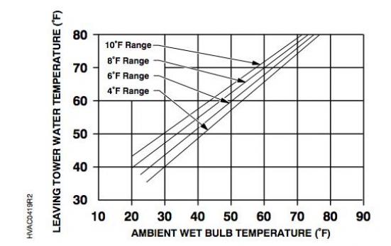
The performance chart illustrates the manner in which the cooling tower’s cooling capacity depends on atmospheric conditions, i.e., the ambient wet bulb temperature. In this chart, the load is quantified in terms of the range (i.e., the temperature difference between the supply and return flows to the cooling tower) and the cooling tower’s water supply temperature [2]. For example, if the building requires cooling tower flow at 40 °F, and the flow experiences a 4 °F increase in temperature as it meets demand (in the Free Cooling heat exchanger), the chart shows that the cooling tower would require the ambient wet bulb temperature to be roughly 30 °F. When designing a new building, this type of chart allows engineers to choose cooling towers that are suited to the building’s cooling demands and local atmospheric conditions in order to maximize the system’s use and reduce energy consumption.
Although performance charts provide a good model of the cooling tower’s ability to meet cooling demands, 41 Cooper Square’s BMS does not utilize this information to control the water-side free cooling system automatically. Instead, the system is operated manually, and activated when operators deem that atmospheric conditions are well suited to the system’s operation.
Wet Bulb Temperature: When discussing a mixture of water vapor and air, the Wet Bulb Temperature is the temperature that a volume of air would have if cooled adiabatically to saturation by the evaporation of water, all latent heat being supplied by the volume of air. This property is usually measured using a wet bulb thermometer or psychrometer. (Measured in Celsius or Fahrenheit) [2]
[1] Cooling Plant Optimization: Application Guide, Rev. 3, Siemens Building Technologies Inc., Munich, Germany, 2003, pp. 122.
[2] Y. Çengel and M. Boles. Thermodynamics: an engineering approach, 7th ed. New York, McGraw-Hill, 2011

